

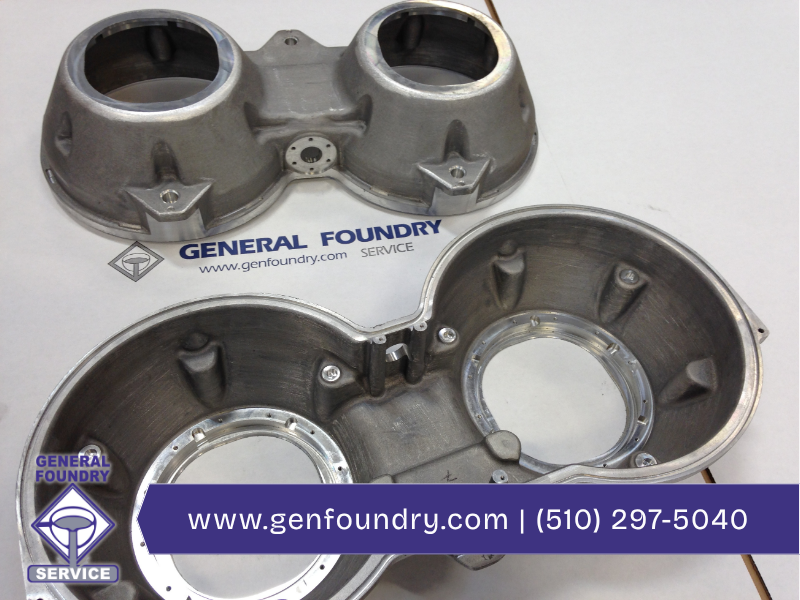
For engineers and procurement specialists designing enclosures, mounts, and RF fixtures for telecom, networking, and GPS systems, sand casting with Aluminum and Zinc‑Aluminum (ZA) alloys remains a cost‑effective route when tight control of thermal, electrical, and dimensional performance is achieved. Here we offer practical foundry‑level guidance to address the top failure modes – porosity, shrinkage, cold shuts, warpage, and misruns – by focusing on gating strategy, mold and core architecture for complex geometries, alloy‑specific melt control, and cooling management. Applied early in the design cycle, these measures reduce rework, accelerate qualification, and ensure cast parts meet grounding, heat dissipation, and mating‑surface requirements critical to modern telecom, networking, and GPS hardware.
Gating strategy for low‑turbulence flow and directional solidification
Gating must be engineered to deliver both a steady mass flow and directional solidification for telecom housings and RF fixtures where internal voids or misruns compromise electrical grounding and thermal paths. Use a bottom-fed runner with a thermally massive sprue and tapered runners sized to maintain Reynolds numbers low enough to avoid excessive turbulence (target Re < 500–1000 depending on alloy) – turbulence entrains air and oxide films that nucleate porosity in Aluminum and ZA (Zinc-Aluminum) alloys. Place well-designed risers and chills to feed sections that solidify last (thin ribs, bosses, and connection flanges common in connectors) and calculate riser volume using solidification modulus; for Al alloys, expect riser-to-casting mass ratios typically 1.1–1.6× larger than for common sand-cast steels because of aluminum’s higher contraction and gas sensitivity. Incorporate filters (ceramic foam or bonded) upstream of the cavity to trap slag and folded oxides, while minimizing pressure drop to avoid misruns in thin-wall telecom brackets.
Mold layout and patterning for complex geometries
Complex multi-feature parts – stacked bosses, precision mounting pads, mating surfaces for RF interfaces – require a pattern and cope/drag layout that prioritizes accessibility for core placement and consistent mold compaction. Design split lines along non-critical surfaces and add drafting for pattern removal, but keep critical sealing faces on the same mold half when possible to reduce post-machining demand. For internal cavities and long, thin passages, use subtractive or hybrid core arrangements (hot-box core prints with metal chaplets for alignment) and specify core hardness and backup supports to avoid deflection during metal filling. For thin fins and heat-sink-like features, anticipate mold erosion; select appropriate sand grain size and binder type to preserve detail without creating excessive permeability that can lead to gas defects.
Alloy-specific considerations: Aluminum vs. ZA (Zinc–Aluminum)
Aluminum alloys used in telecom enclosures offer favorable strength-to-weight and thermal conductivity. ZA alloys fill more readily and capture detail but have narrower pouring windows and different solidification shrinkage characteristics; gating must account for ZA’s higher fluidity but greater tendency for hot tearing in restrained sections. Specify target chemical compositions and acceptable impurity limits up front, and qualify supplier lot-to-lot variability; ensure melt temperature control within ±10–15 °C of the alloy’s optimal pouring temperature to avoid misruns and cold laps while minimizing microporosity.
Thermal management and cooling strategy
Thermal gradients drive defects and dimensional variation. Use chills at high-modulus areas to accelerate solidification, preventing shrinkage cavities from forming (e.g., thick bosses adjacent to thin flanges). For flat mating faces, control cooling to reduce warpage by balancing section thicknesses or adding conformal chills; consider temporary metal chills in the mold to moderate cooling rates for features that require tight flatness. Predict cooling with finite-element solidification simulation (modulus and thermal gradient mapping) to locate hot spots and size risers/chills; validate simulation inputs with measured thermal conductivity and specific heat values for the chosen alloy and sand system.
Sand system, permeability, and venting
A sand matrix and binder system that balances fine detail reproduction and gas permeability is necessary for better surface finish for RF-contact faces. The finer sand can reduce permeability – but that can be compensated by adding venting channels, vein vents, or coarser backup sands behind critical faces. For Aluminum alloys, implement directional venting paths and vacuum or controlled venting for enclosed cavities where trapped air would generate blowholes. Specify permeability and compressive strength targets for the mold and cores, and QA them through simple bench tests (permeability number, collapsibility) tied to expected molten metal velocities.
Tolerancing and post-cast operations to meet telecom specs
Because casting tolerances for sand-cast Aluminum and ZA are coarser than those for machined parts commonly used in networking and GPS hardware, define function-driven tolerances: keep critical mating surfaces and threaded inserts as net-shape only where possible; otherwise, specify boss diameters and mounting pad stock allowances for consistent machining. Use cast-in inserts or conformal metallic inserts when repeated assembly torque or EMI grounding requires metal-to-metal contact. Specify inspection points and establish Cpk targets for critical dimensions; iterate on pattern/tooling adjustments based on first-piece CMM data.
Process controls, inspection, and qualification
Implement statistical process control on key parameters: pouring temperature, melt hydrogen level, sand permeability, core hardness, and cope/drag compaction energy. Use X‑ray or CT sampling for porosity analysis during qualification runs (especially in feed-throughs and RF grounding areas) and correlate defect patterns with gating/mold layout to enable corrective actions. Maintain documented alloy lot traceability and perform mechanical/thermal property testing (tensile, thermal conductivity, and CTI, where applicable) on initial production batches to verify conformance with telecom and GPS operational requirements.
Action items for design engineers
- Early-stage: provide a section-thickness map and highlight critical mating/grounding faces.
- Material spec: declare alloy grade, max hydrogen tolerance, and required thermal/mechanical properties.
- Pattern/coring: indicate internal cavities and allowable core print locations; prefer single-mold-half critical faces.
- Tolerance/finish: call out net shape vs. stock-for-machining and the allowable surface roughness for RF contact areas.
When applied early and enforced with data-driven controls, these practices cut scrap and rework, accelerate qualification, and produce sand‑cast Aluminum and ZA components that reliably meet the electrical grounding, thermal dissipation, and dimensional stability requirements of telecom, networking, and GPS hardware.
How can General Foundry Service help you?
Five Casting Processes. One Roof. Zero Compromises. General Foundry doesn’t force your design into a single method. With five in-house casting disciplines – Green Sand, No‑Bake, Permanent Mold, Rubber Plaster Mold, and Investment Casting – plus in-house patternmaking, 16 CNC machines, and full finishing under one roof, we select the optimal process for your geometry, tolerances, finish, alloy, and production volume. Our engineers take a “first-time-right” approach, matching design intent to process capability early so you get the results you need without costly rework. Contact us todayfor more information or to get started on your next project